I. HIL-1000 and HIL-C1
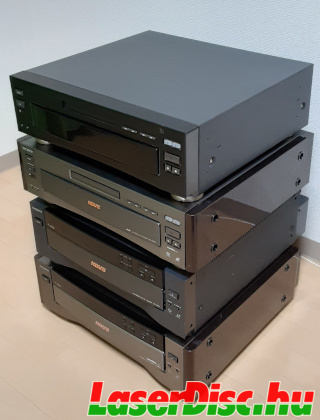
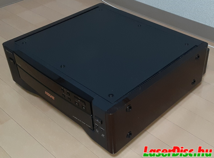
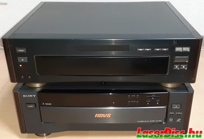
HIL-1000 is the so called "industrial" version of the HIL-C1, or HIL-C1 is the consumer version of the HIL-1000 if you like (see Fig. 1. and Fig. 4.).
And there's the Panasonic LX-HD10 (see Fig. 3.), which is also a HIL-C1 with some cosmetic changes.
Quite interesting, that according to
an article on LaserDiscArchive UK [1], the LX-HD10 was the first Hi-Vision player on the market (May 20th 1994), released just before the HIL-C1 (June 1994).
HIL-C1 received a
"Good Design Award" (Award no. 93B0157) [2], and there they state the date was 1993/5/12.
Sony's official "Company history" site [3] also states 1993 for HIL-C1.
Anyway, they all seem to be very similar, and so they are, but there are some differences.
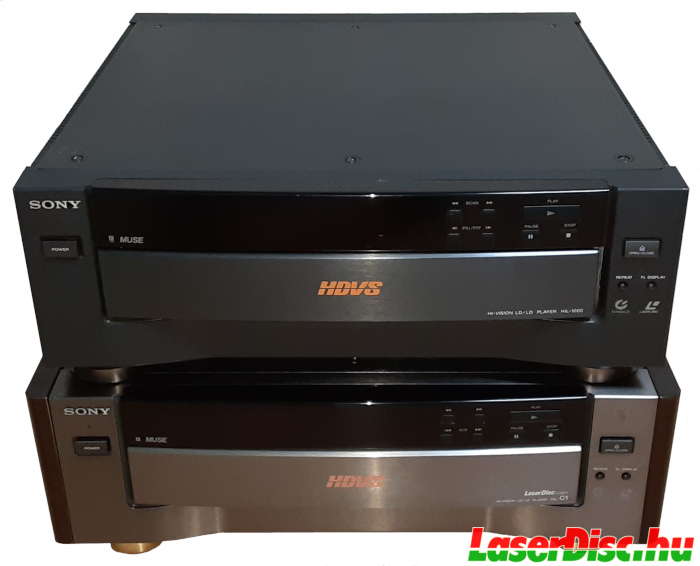
Fig. 1. Sony HIL-1000 and Sony HIL-C1 - Front.
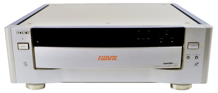
Fig. 2. Sony HIL-C1 - Gold finish.
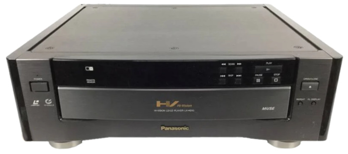
Fig. 3. Panasonic LX-HD10 - Front.
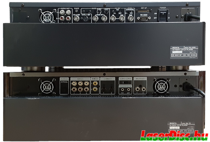
Fig. 4. Sony HIL-1000 and Sony HIL-C1 - Back side.
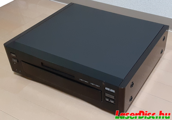
First, comparing the exterior of the HIL-1000 to the HIL-C1, the HIL-1000 has:
- Simple black finish (which is actually pretty nice)
- No wooden side panels
- Silver legs, not gold
- A way different back panel (details follow)
- "IRPro" logo on the front (not just "IR" - see Fig. 35.)
HIL-C1 back panel (Fig. 4., Fig. 5. and Fig. 9.):
- Mode switch (only on gold HIL-C1)
- Digital audio out (TOSLINK)
- 3x 2 channel audio out (RCA)
- 2x Composite video out (RCA)
- 2x S-Video out
- LDP1/2 switch
- Wired remote control in/out jacks
- 2x MUSE out (RCA)
- 2 fans
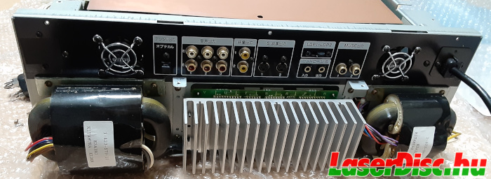
Fig. 5. HIL-C1 back panel.
HIL-1000 back panel (Fig. 4. and Fig. 6.):
- 2x 2 channel audio out (RCA)
- Remote
- Composite video out (BNC)
- S-Video out
- MUSE H. Shift switch (hidden - see: Fig. 7. and Fig. 8.)
- MUSE Horizontal Adjust knob
- MUSE Vertical Shift knob
- 2x MUSE out (BNC)
- HD REF IN (BNC)
- HD REF OUT (BNC)
- HD REF 75 Ohm ON/OFF switch
- SYNC GENERATOR ON/OFF switch
- SYNC GENERATOR OUT (BNC)
- "SET UP" DIP switch
- RS-232C port
- Power switch
- 1 fan only
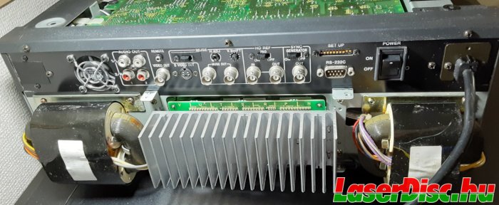
Fig. 6. HIL-1000 back panel.
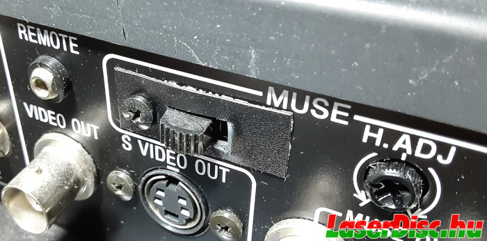
Fig. 7. HIL-1000 back panel - Hidden label.
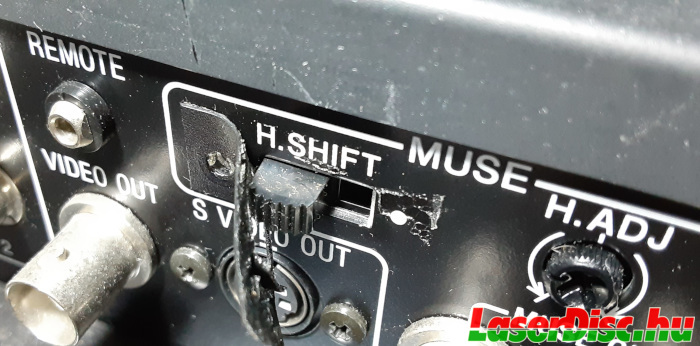
Fig. 8. HIL-1000 back panel - Hidden label uncovered.
The gold finish version of the HIL-C1 has the "Mode Switch" (see section
I.1.1. for more details) exposed on its back (see top left in Fig. 9.), while on the black HIL-C1 and on the HIL-1000 those are covered with a small plastic sheet.
Although the functions of these switches are unknown (yet), the switches are included inside in the black models also.
Maybe the "Mode Switch" were covered later, and that could suggest (along with the low serial number on the only golden HIL-C1 I have ever seen online) that a few golden ones were manufactured first,
then the black ones which are a bit updated versions.
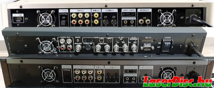
Fig. 9. HIL-C1 gold, HIL-1000 and HIL-C1 black back panel
I.1. Inside the HIL1s
So what's in the box?
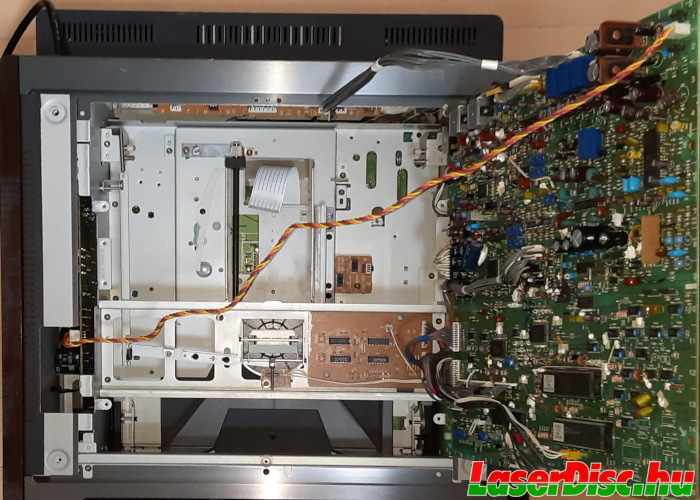
Fig. 10. HIL-C1 opened up - tray out.
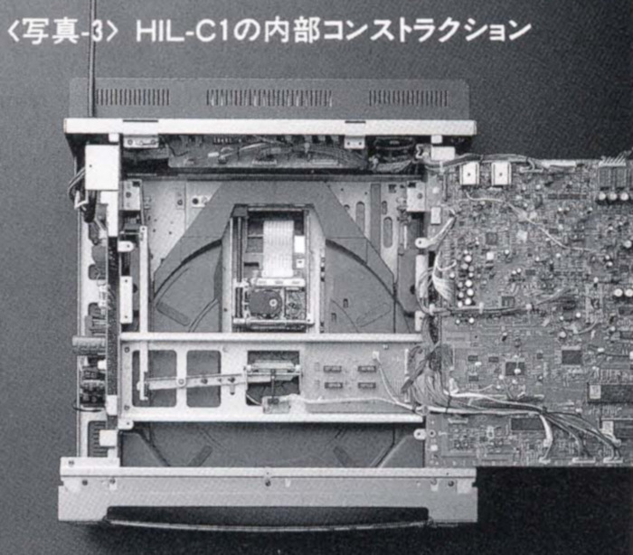
Fig. 11. HIL-C1 opened up - From Sony's "Technology Now" brochure.
"Photo-3. HIL-C1's internal construction" [4]
The top board (SA-701 - see right side of Fig. 10. and Fig. 11.) contains the "System Control"
Hitachi H8/325 microcontroller [5] (IC105) and the "Interface control"
Mitsubishi M37451 microcontroller [6] (IC114) (see Fig. 12.).
The Hitachi (IC105) one has 32Kbytes of on-chip ROM an 1Kbyte of RAM, the Mitsubishi MCU (IC114) has 16Kbytes of ROM, and 384 bytes of RAM.
Oddly enough the HIL-1000 was equipped with an older system control software version, but with a newer interface control software version than the C1.
The SA-701 of the HIL-1000 has the components for the serial port (see more details in a later section), and also it seems to be a newer revision of the PCB than my HIL-C1s.
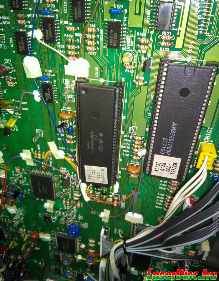
Fig. 12. Microcontrollers on the SA-701 mainboard.
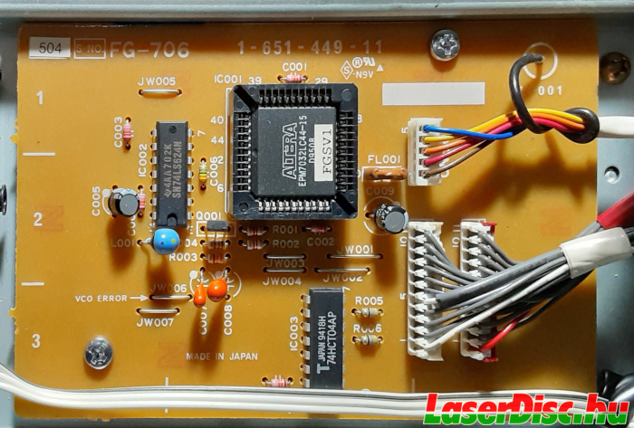
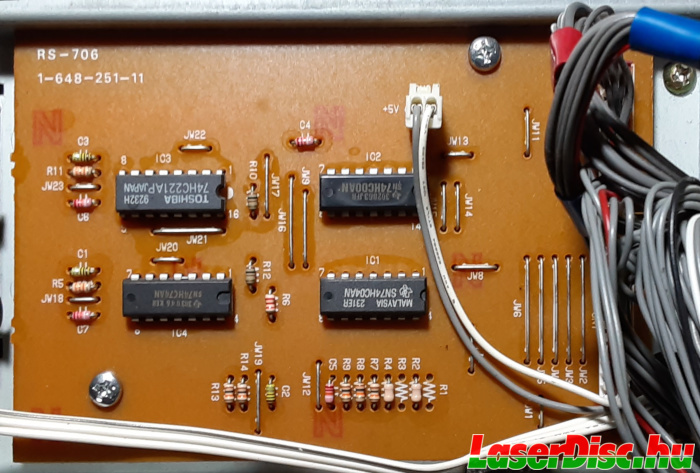
The first difference that can be easily noticed, that instead of C1's RS-706 board, HIL-1000 has the FG-706 board near the clamper. FG-706 contains an Altera PLD with an "FGSRV1" (program version probably) sticker on it, RS-706 only has simple ICs (hex inverter, multivibrator, nand gate, flip-flop). In some C1s, this board does not have the RS-706 marking.
The left side power PCB (PW-702) and
The power/servo control PCB (SP-702) on the right side are different revisions (see Fig. 15. and Fig. 16.), probably not related to C1/1000 model features/differences.
The newer revision in the HIL-1000 has some newer type SMD components, R007 was replaced by a fuse, some caps on left side are different, most of the components from SP-703 (see Fig. 17.) were moved onto SP-702, so the middle and right part of the board became a bit more dense.
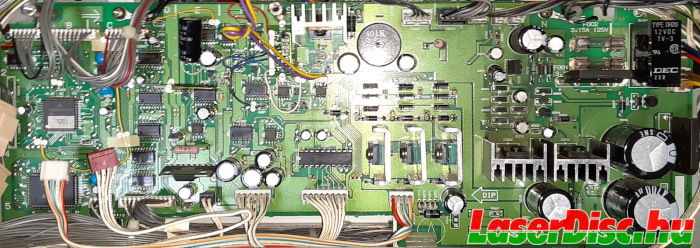
Fig. 15. SP-702 board older revision.
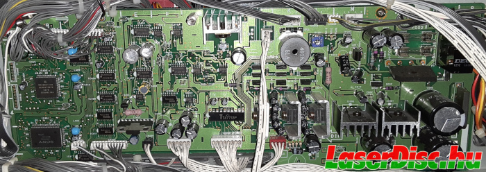
Fig. 16. SP-702 board newer revision.
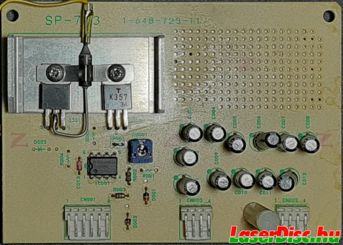
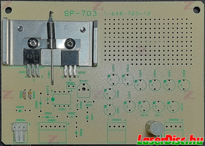
Fig. 17. Different SP-703 boards. (Move the slider to compare.)
Opening up the bottom reveals some more differences (Fig. 18.).
The SL-704 (see Fig. 19.) board on the left is absent in the C1's, probably this is the one which is responsible for the sync generator, hd ref, and adjustments available on the back panel of the HIL-1000.
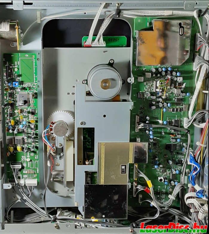
Fig. 18. HIL-1000 - Looking from below.
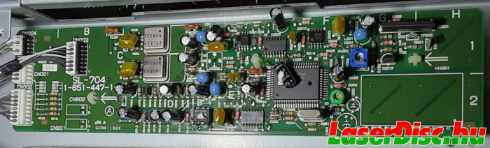
Fig. 19. HIL-1000 - SL-704 board.
Also the bottom motherboard (MV-701, see Fig. 22.), probably responsible for processing the MUSE video signal, has a daughterboard labeled IT-701 (see Fig. 23.), with an OKI M10S0110-030 (i have no info what it does) chip sitting on it (see Fig. 24.).
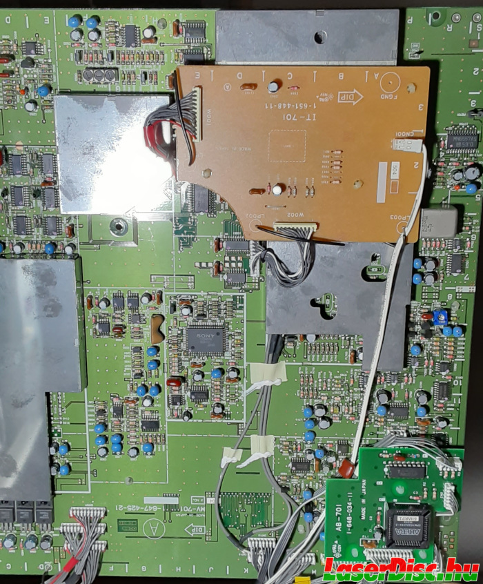
Fig. 22. HIL-1000 Bottom mainboard (MV-701).
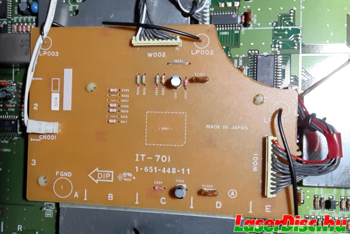
Fig. 23. HIL-1000 IT-701 board on MV-701 - Top.
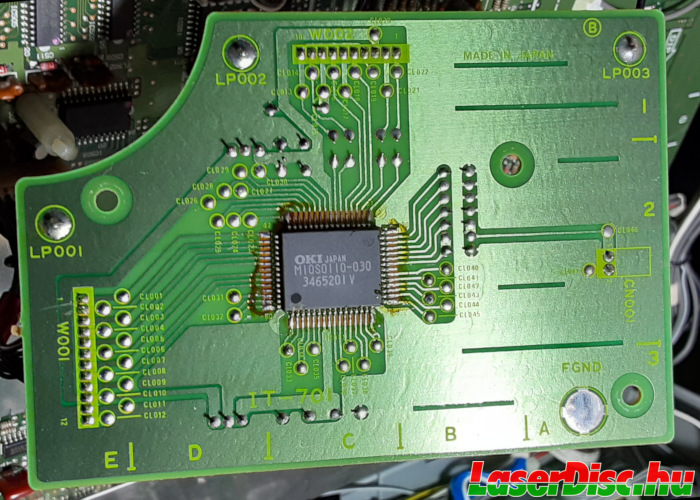
Fig. 24. HIL-1000 IT-701 board on MV-701 - Back.
I.1.1. The "Mode Switch"
The "Mode Switch" has 4 switches (DIP switch mounted on the SE-701 board), without any markings.
According to the service manual, they are connected to the AB-701 board (see Fig. 30.)
and wire SW1 is marked as "SHARP", SW2 wire is marked "MATSU", SW3 and SW4 are not used (see Table 1.).
Although the mention of SHARP can suggest that the AB-701 is doing some video enhancement, but maybe these ("SHARP"/"MATSU") refer to
company names. Matsushita (Panasonic) has an OEM player (LX-HD10), maybe Sharp also planned to sell HIL-C1 under their name, and these switches change the behavior of the player to adjust them to the needs of Sharp/Panasonic?
It's just my guess, please don't take it as a fact :-)
| Mode Switch - SW no. | Description |
| 1 | SHARP (Sharp?) |
| 2 | MATSU (Matsushita/Panasonic?) |
| 3 | NC |
| 4 | NC |
Table 1. Description of the "Mode Switch" switches.
I.2. Dumping the programs of the main MCUs
As IC105 and IC114 are seated in sockets, one can remove them from the mainboard quite easily (if you do so, be sure to use an appropriate tool and be very careful not to bend/break the pins).
Fig. 25. shows the temporarily removed MCUs both from a HIL-C1 (left) and from a HIL-1000 (right).
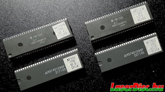
Fig. 25. Microcontroller Units found in Sony HIL-C1/HIL-1000 players
According to their data sheets [5] [6], the two MCUs can be set to PROM mode and then their contents can be read out.
So i've prepared a simple program for an Arduino Mega, which just does that.
For more info (source code, wiring, etc.) see:
https://github.com/szaguldo-kamaz/mcuromread/ [7].
I.2.1. SDIP64 to DIP64
As the MCUs are Shrink DIP packages, i had to get a SDIP64/DIP64 adapter PCB to make the wiring easier.
A couple of different types are being sold online, for me,
Kadanken's version [8] was the easiest to obtain.
I soldered an IC socket and two rows of female headers on the DIP64 side, because i wanted to directly attach it to the Arduino with jumper wires (see Fig. 26. and [7]).
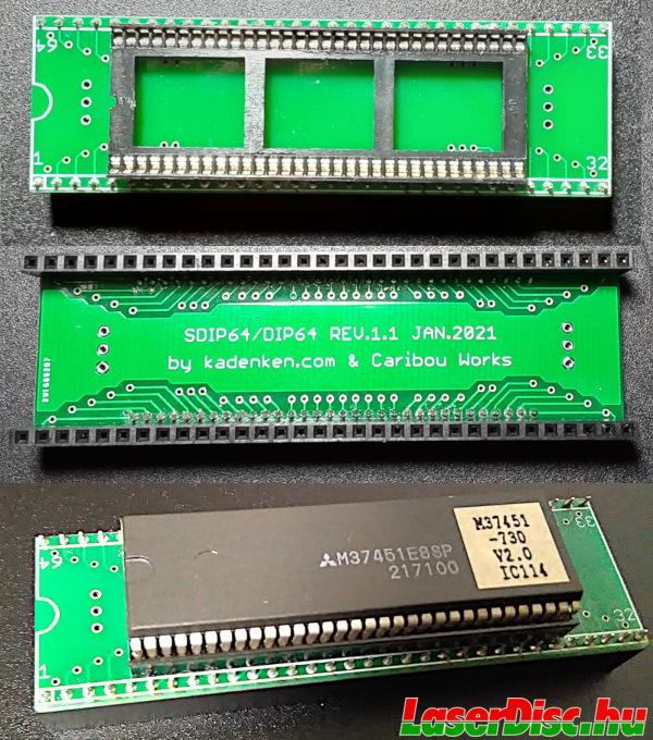
Fig. 26. SDIP64 - DIP64 adapter.
I.2.2. ROM versions and about the code
To avoid possible copyright violations i decided not to share the ROM images, only their CRC32 and SHA1 checksums (see Table. 2.).
| Model | MCU | CRC32 | SHA1SUM |
| HIL-1000 | M37451E8SP
M47451-147 V2.1_IC114 | 9ea53e6e | 14f917e6e86633b2dca71f5d4e6eb9466c6dc989 |
| HIL-1000 | H8/325 HD6473258P10
6473258-147 V2.1_IC105 | 98f7b33f | ab3e6ea1a94ce583bafb95a601c27316247d670d |
| HIL-C1 | M37451E8SP
M47451-730 V2.0 IC114 | 723cd559 | 4a4510e96e36973bde9878e63d6935ba771dbf06 |
| HIL-C1 | H8/325 HD6473258P10
6473258-730 V2.3_IC105 | 3dc1f8f2 | ed28dde6a21719c40ad9dff1f14154fe4d9ae15a |
Table 2. Checksums of the retrieved ROM images.
HIL-1000 had IC114 V2.1, IC105 V2.1, HIL-C1 had IC114 V2.0 and IC105 V2.3. I also had IC105 with printed V2.2 labels, which were corrected with a red ink pen to V2.3 (see Fig. 27.).
Maybe those were just mislabeled, but it's also possible that only tiny modifications were made compared to V2.2, which only changed 1s to 0s in the ROM, hence those parts could be overwritten.
Anyway they contained the same code as the ones with printed V2.3 labels:
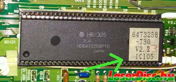
Fig. 27. IC105 with corrected V2.3 label
I know about the existence of V2.4 IC105s, but i don't have any of them (yet).
So if you own a HIL-C1/HIL-1000, and dump the ROMs you can check whether they match these or not.
Or you can load it back into an empty MCU (maybe with some custom mods), as you can still
buy unused ones [9].
Just an interesting part, proving that the data was dumped correctly from the H8/325: Fig. 28. shows a tiny part of the hex dump of the ROM image, the strings which are sent probably to the OSD character generator.
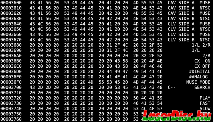
Fig. 28. ASCII strings in HIL-1000's H8/325 MCU ROM dump
Actually these are the only interpretable ASCII strings in the ROM of the
HD6473258P10 [5].
The data structure and the code also seem to make sense. The vector table looks normal.
The reset vector points to 0x0100, so that's where the actual code should begin.
With the help of an
H8/300 disassembler [10], i checked on the code from there.
The program begins with zeroing the RAM in the MCU and things like that. So it looks totally OK.
About the
M37451E8SP [6]. The ROM size is 16Kbytes, but when reading from the ROM, the 0x0000-0x3fff (first 16Kbytes) region showed only zeroes, then from 0x4000-0x64FF all 0xFF. Then some data began at 0x6500.
When the MCUs is in normal operation, the 16Kb ROM should be mapped in the higher region, so in case of 16Kbytes, in the 0xC000-0xFFFF region.
The interrupt vector table is at the end of the ROM in the 0xFFE0-0xFFFF range.
And the reset vector should be the last one (0xFFFE), which in this case points to 0xE500.
Which is exactly 0x6500 in the dumped ROM image, where the data seem to start.
Interpreting the data at 0x6500 (0xE500) as MELPS740 machine code, it quickly turns out that those are valid opcodes for clearing state flags, and things like that for initialization.
Therefore, this dump also looks fine. Anyway, this one doesn't seem to contain much code.
The first 16Kbyte can be cut from the image as that was not a valid ROM region, e.g. by using dd:
dd if=dump_m37451e8sp__32kb.bin of=dump_m37451e8sp__16kb.bin count=1 bs=16k skip=1
I've added "support" for the M37451 in this nice
MELPS740 disassembler [11], so it can generate an assembly program for HIL's "Interface Control".
Reverse engineering the code is a future project...
I.2.3. Other MCUs and PLDs
There's another MCU (IC402 "System Control") on the SP-702 board (right hand side).
It is a
Motorola MC68H11 [12] family MCU (MC68HC711E9FU-SP) in a 64-pin QFP package (surface mounted, see Fig. 29.), so a bit harder to access (actually many pins are also available as test points on the PCB).
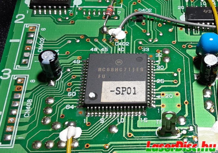
Fig. 29. Motorola MC68HC711E9 on SP-702 board loaded with "SP01"
Also there is an Altera EPM7032 (EPM7032LC44-3) PLD labeled with "SHARP1" sitting on a daughterboard (AB-701) on top of the bottom mainboard MV-701 (see Fig. 30.)
This SHARP1 uses the first two switches from the "Mode switch" as inputs.
In the HIL-1000, another Altera EPM7032 PLD (EPM7032LC44-15) can be found on the FG-706 board, labeled with "FGSV1".
These ones could be also worth investigating later. The other ICs are mostly custom Sony chips (probably ASICs) with not much or no available documentation.
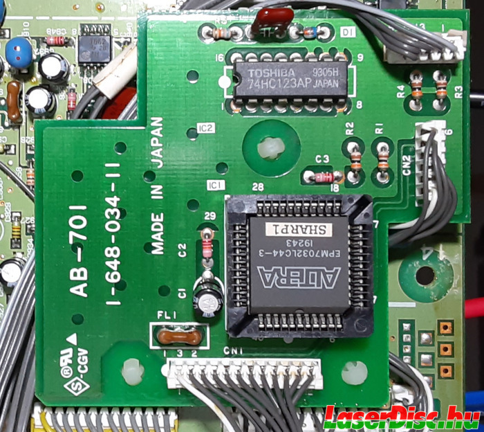
Fig. 30. AB-701 daughterboard with an Altera PLD loaded with "SHARP1"
I.3. IR Remote control
HIL-C1 comes with the RMT-M18 remote (see Fig. 31.), supporting the two different SIRCS protocols (LDP1/2 switch).
The RMT-M18 has two versions, the black one is the common one, the other one is quite rare, it is a gold edition for the HIL-C1 with gold finish.
The gold one is missing the "Hi-Vision LD" logo, which the black one has. The black one has a green "power" button, while the gold one uses the same color as for other buttons.
These also suggests that the gold editions were made before the black/silver ones, and the latter ones had small updates on them.
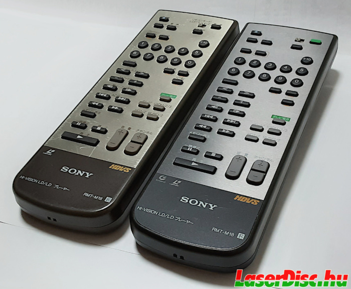
Fig. 31. RMT-M18 - IR Remotes for HIL-C1
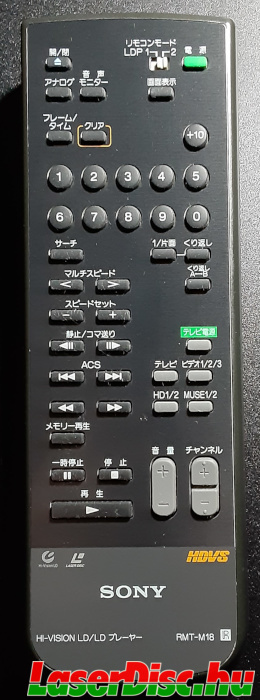
Fig. 32. Black RMT-M18
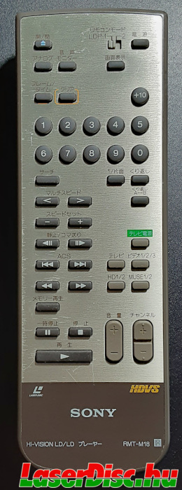
Fig. 33. Gold RMT-M18
Fig. 34. Black and gold RMT-M18 remotes. (Move the slider to compare.)
RMT-M18 does not work with the HIL-1000 by default (remember the IRPro logo on the front panel? - see Fig. 35.).
A
certain website [13] mentions a "sold separately" remote control model as "the" remote for HIL-1000, but probably that's just a remote supporting the IRPro protocol, not the "original" HIL-1000 remote (if there was any?).
Actually, the mentioned remote (RM-2001A) seems to be a quite older Lasermax/LaserVision remote, speaking IRPro.
(Buy maybe there is a HDVS RM-2001A too, using the same type no.).
The IR receiver hardware is still the same, the difference is only in the software decoding the signals:
I've replaced IC114+IC105 in the HIL-1000 with ones from a HIL-C1 and in that configuration the RMT-M18 (tried in LDP2 mode) started working with the HIL-1000.

Fig. 35. IR logo on HIL-C1, IRPro logo on HIL-1000.
Regarding the Panasonic LX-HD10, the remote is somewhat different from the original Sony one.
I did not have the chance to try this remote, but the IR codes can be also different
(like with the LX-HD20, see section
II.1.1.).
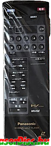
Fig. 36. LX-HD10 IR remote.
I.4. KHS-140A optical unit
HIL-C1 and HIL-1000 use the KHS-140A optical pick-up unit (see. Fig. 37. and Fig. 38.).
Since they are not auto-reverse players, the optical units move only back and forth on one fixed linear path.
The tilt servo motor is on the OPU itself, the SKS-2M and the SKS-1 boards are both responsible for controlling the tilt servo motor.
SKS-1 on the bottom (see. Fig. 39.) is also responsible for creating the RF signal from the signals coming from the photosensor array.
The PP-21M under the side metal cover (with the KHS-140A S/N sticker) contains the photosensor array (see Fig. 44. and Fig. 45.).
The AP-13 board and the small board under the bottom metal cover are for controlling the laser diode output.
And of course a metal assembly in the middle for holding the collimator lens, half mirror, etc. in order to create the right optical paths for the laser beams.
These sandwiched together make up the KHS-140A optical pick-up.
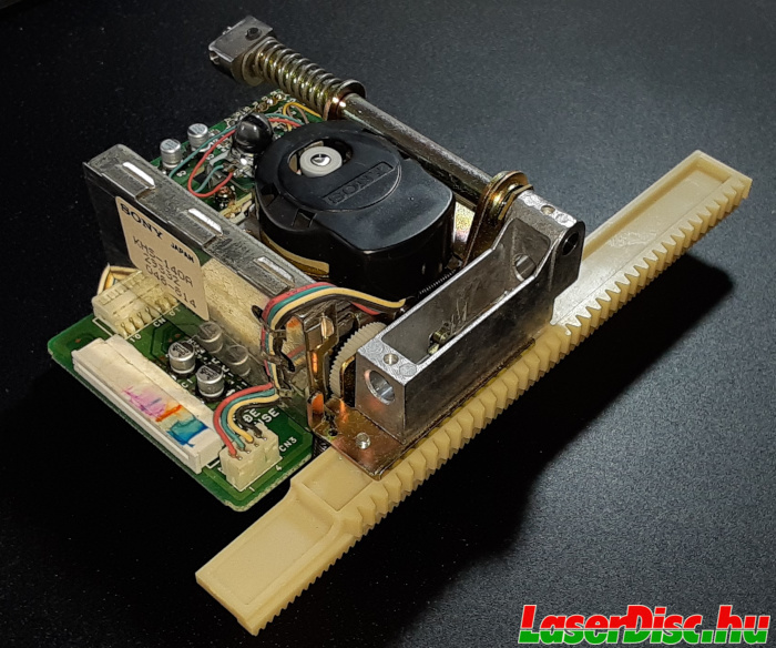
Fig. 37. KHS-140A optical pick-up 1.
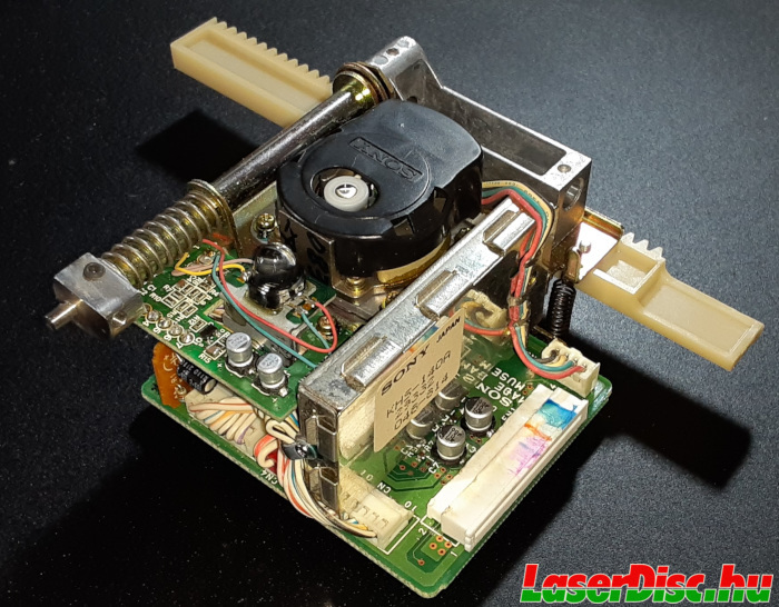
Fig. 38. KHS-140A optical pick-up 2.
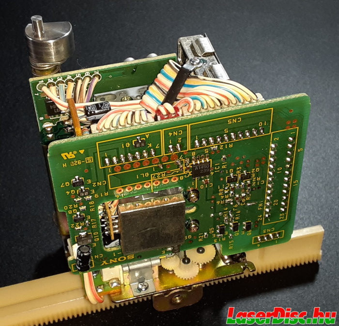
Fig. 39. Bottom of the KHS-140A optical pick-up.
I.4.1. Revisions
There should be at least two revisions, as the KHS-140A optical unit used in my HIL-1000 is a bit different than in the C1s.
On the SKS-2M board R15 and C7 are populated separately, on the KHS-140A units i've seen in HIL-C1s, have this cap soldered on top of R15, and no place/marking for C7 (see Figs. 40., 41., 42.).
Probably it's not a HIL-1000/HIL-C1 difference, only the installed KHS-140A OPUs were different revisions, probably the one with the separate C7 being the newer revision.
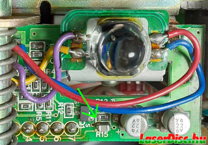
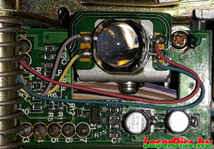
Fig. 40. Slightly different SKS-2 boards. (Move the slider to compare.)
Furthermore, it seems that the tilt sensor was originally meant to be connected to the SKS-2M board by a flat ribbon cable, but was cut and replaced by red/blue/yellow/purple wires hand soldered (see Fig. 43.).
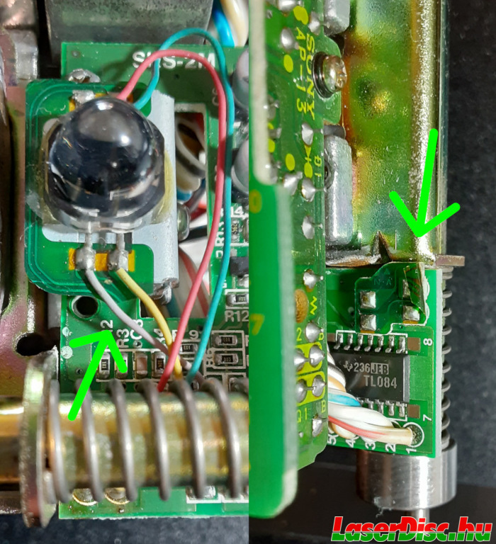
Fig. 43. Original tilt sensor connection (top view - left, bottom of SKS-2M - right).
I.4.2. KHS-140A photosensor array
The photosensor array found on the PP-21M board in the KHS-140A is shown in Fig. 44. Notice the excess solder on a pin on the left, actually it's not a problem, just interesting.
Fig. 45. shows the sensor a bit closer and with different light reflections, so the quadrant sensor for detecting focus errors and for obtaining the RF signal itself and the two side sensors for tracking can be seen clearly.
The second order beams have much lower intensity than the first order beam (see Fig. 47.) hitting the quadrant sensor (A/B/C/D), that could be one reason for the larger area of the E and F sensors.
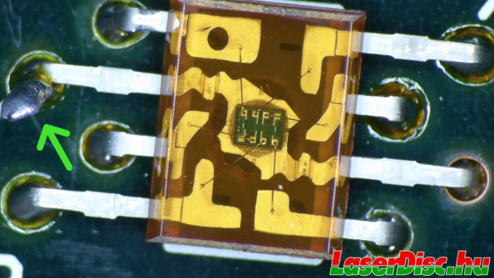
Fig. 44. Photosensor array of the KHS-140A.
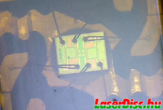
Fig. 45. Close-up of the photosensor array in the KHS-140A.
I.4.3. KHS-140A laser
As KHS-140A employs a 670 nanometers wavelength (red) laser diode, so the human eye can see the laser (mostly we see the reflections when it is scattered from a surface it hits).
But be very very careful not to look into the laser beam(s).
The lasers in LD players are strong enough to cause damage to the eyes.
Please don't do these things if you don't know what exactly you are doing!
Fig. 47. shows the different order beams hitting my ceiling coming from the laser through the grating and the collimator lens (i've removed objective lens temporarily), approximately 1.5m from the KHS-140A sitting on a table (see Fig. 46.).
The beams are exponentially losing from their intensity compared to the first order beam (the middle one).
In Fig. 47. only 8 are visible (a bit more fuzzy than it was in reality, but this was the best shot i could take), but i could count till the 11th order beam.
The 1st order beam is reflected back on the quadrant sensor (A/B/C/D), and the two 2nd order beams are reflected back from the disc into the two tracking sensors (E/F) (see Fig. 45.).
The usual split beams (i remember doing the same with a gas laser based Philips VLP-720 and getting the same pattern) projected onto a piece of paper towel (hence the "dotted" pattern) can be seen in Fig. 48.
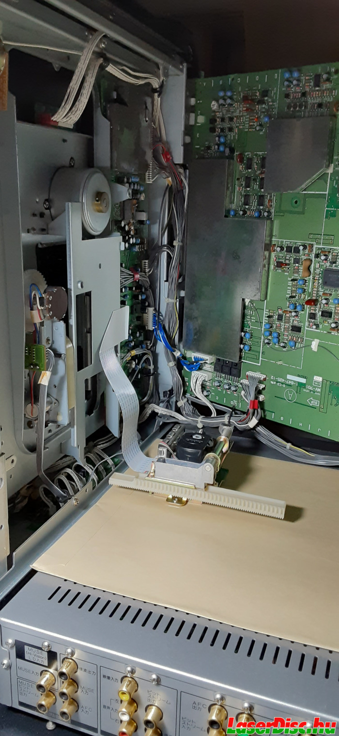
Fig. 46. Workbench for experimenting with the KHS-140A.

Fig. 47. Some of the different order beams (1st order beam in the middle).
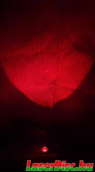
Fig. 48. Beams projected onto a paper towel.
The intensity of the laser diode is controlled based on the feedback from a photosensor right next to the laser diode.
The control circuitry is on the AP-13 and a smaller PCB (see. Fig. 49.) found inside a metal housing. Two wires for the laser power control and two wires for the photosensor.
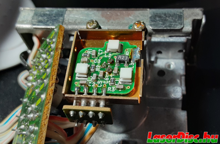
Fig. 49. Bottom of the PCB with the laser diode.
The CN4 connector on the SKS-1 PCB is directly connected to the FN1 flat ribbon cable, so the AP-13 and the RF-702 board are directly connected.
Probably CN4 is only used for turning the laser on and off.
I.4.4. KHS-140A focus and tracking
The focus and tracking coils are connected to the flat ribbon cable (FN1 connector) directly through CN4 on the SKS-1 board.
After removing the black plastic protective cover from the top of the objective lens part, tracking / focusing coils along with their corresponding permanent magnets are revealed (see Fig. 50. and Fig. 51.).
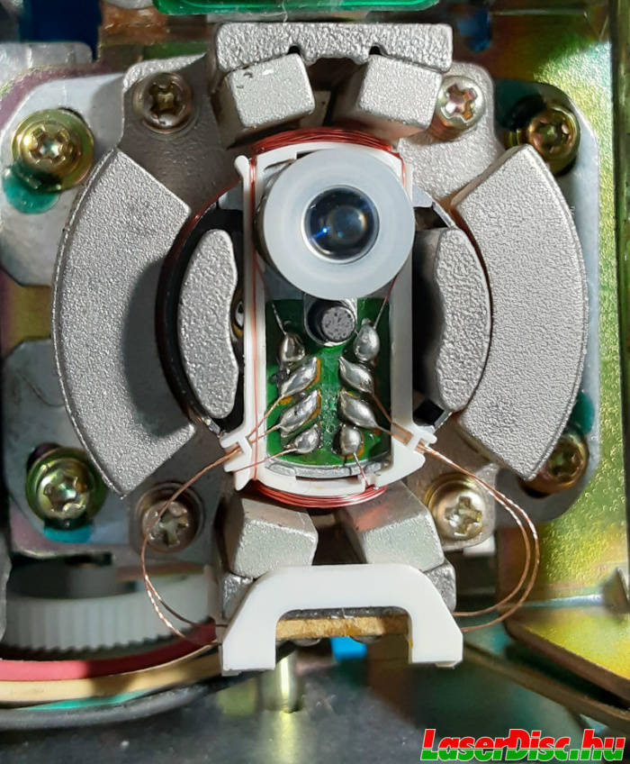
Fig. 50. Focus and tracking coils for moving the objective lens.
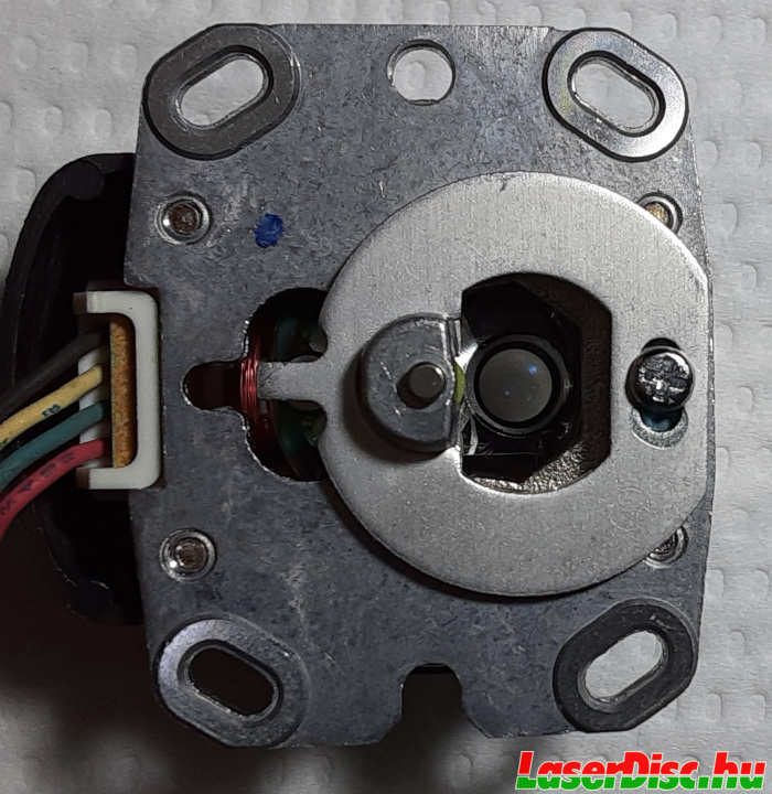
Fig. 51. Focus and tracking coils for moving the objective lens - Bottom.
I.4.5. KHS-140A on fire
Sadly, this one probably executed the Halt and Catch Fire instruction (see Fig. 52. and Fig. 53.).
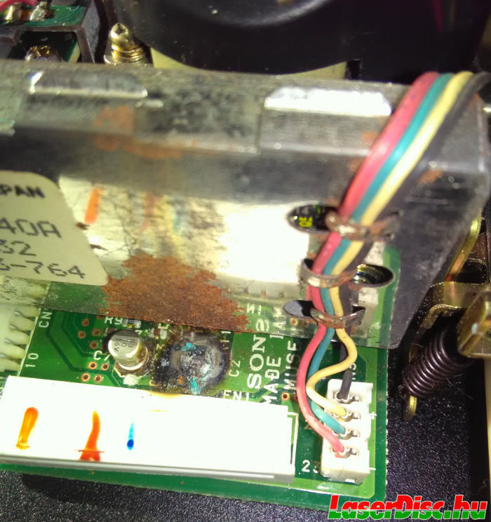
Fig. 52. Halt and Catch Fire.
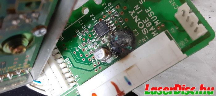
Fig. 53. Halt and Catch Fire 2.
I.5. Serial port on HIL-1000
The RS-232C port on the HIL-1000 is a male DB9 connector. HIL-1000's serial port looks pretty standard in every way.
But before i connected it to a PC, i've checked and traced the pins, seems to be the standard pinout.
Signal levels from the HIL-1000 RS-232C port were around 9V, which is fine.
Pin numbering can be also seen inside the connector, see Fig. 54.
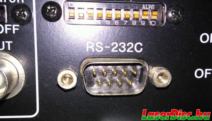
Fig. 54. HIL-1000 RS-232C port.
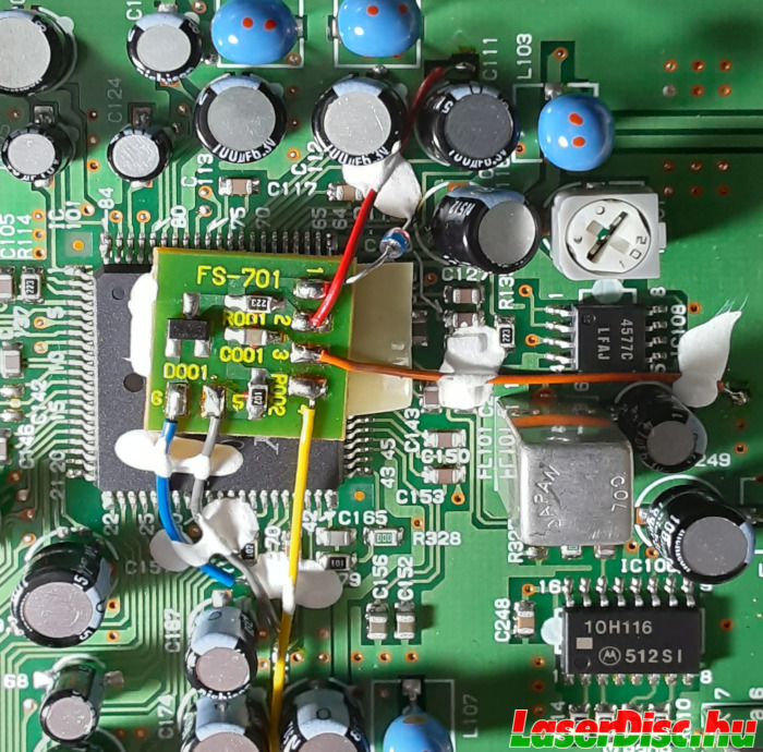
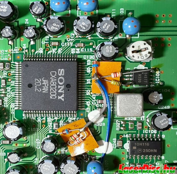
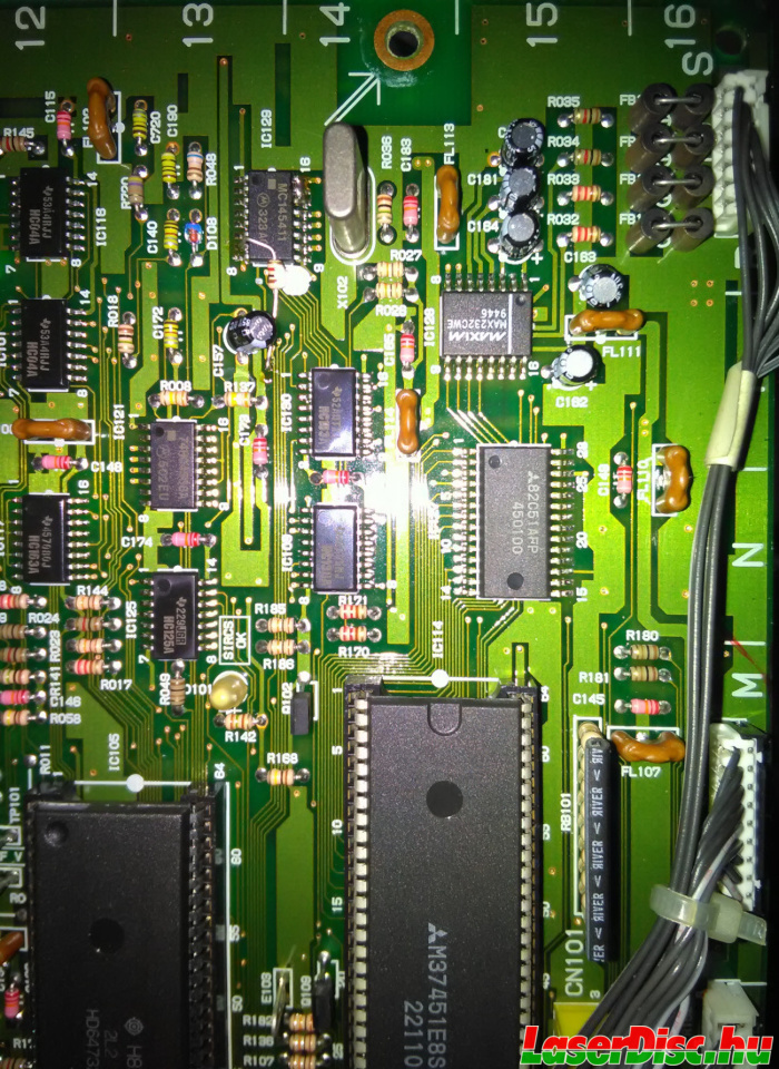
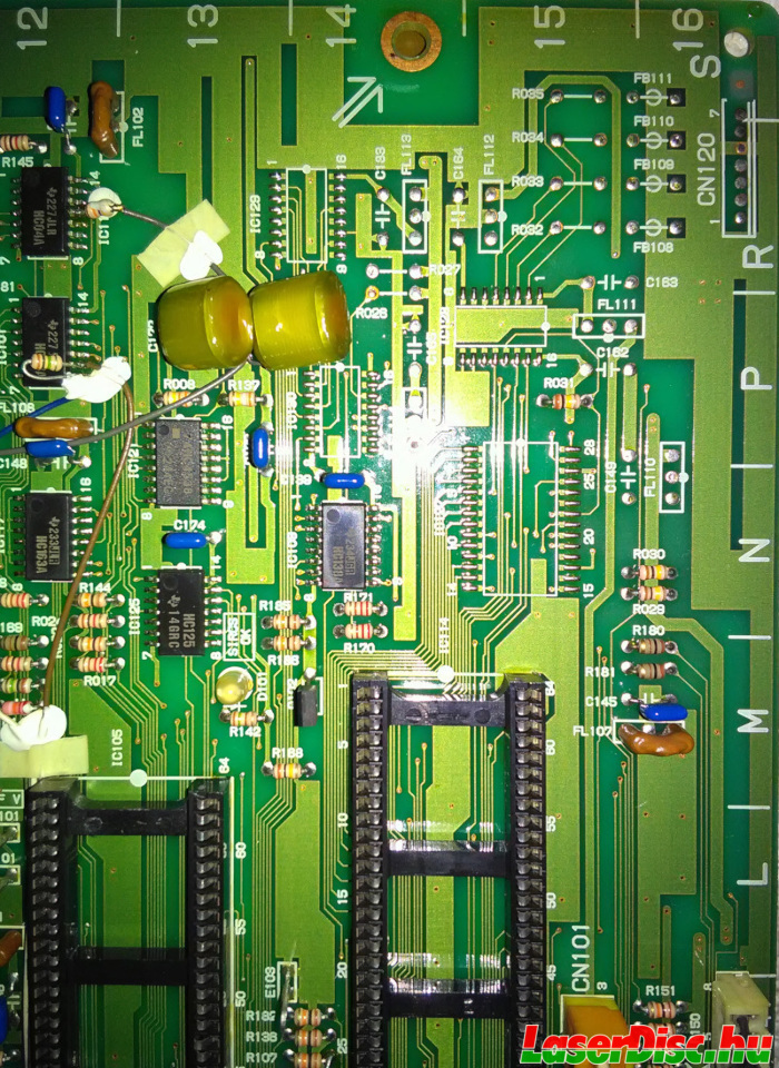
The following figures show the components for realizing the serial interface: 82C51 UART by Mitsubishi, MAX232 level shifter, MC145411 bit rate generator, crystal, caps, resistors etc.
The two mainboards are different revisions, you can discover many differences, HIL-1000 seems to be using a newer revision of the mainboard (although the software version of IC105 is lower).
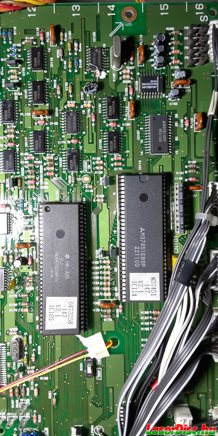
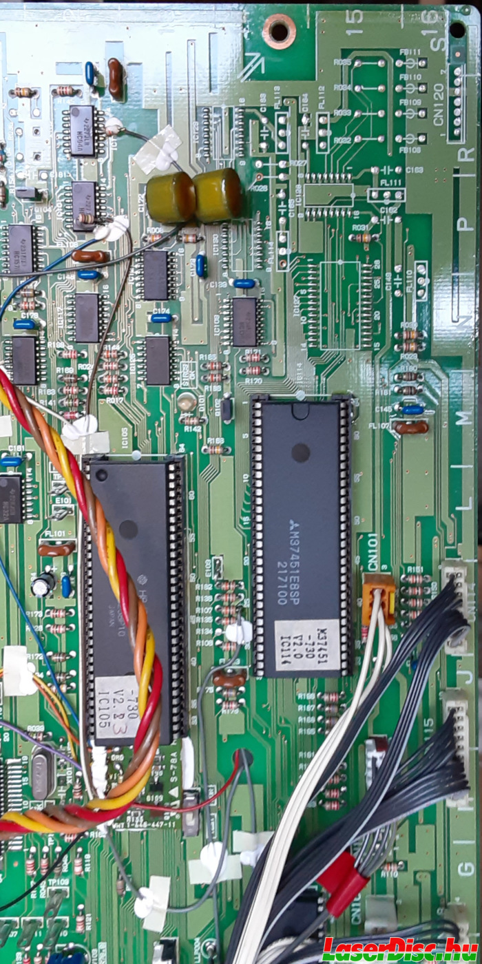
Fig. 55. Serial port related components on SA-701 in HIL-1000/HIL-C1. (Move the slider to compare.)
I.5.1. RS-232C pins
The pin configuration on the back of the HIL-1000 (Fig. 54.) is standard as illustrated in Fig. 61., where the top left is pin 1, the bottom right is pin 9.
--------------
\ 1 2 3 4 5 /
\ 6 7 8 9 /
-------- |
Fig. 61. Pin numbering of the HIL-1000' serial port.
The connections from the RS232-C port to the UART are shown in Table. 3. and Table. 4. (CN120 connects the back side serial port DB9 connector to the SA-701 mainboard):
| RS-232C | CN120 | Via | MAX232 | Remark |
| pin 2 | pin 3 | FB110 and R034 | pin 13 | R1 IN ← PC Tx - RX (in) |
| pin 3 | pin 1 | FB108 and R032 | pin 14 | T1 OUT → PC Rx - TX (out) |
| pin 4 | pin 2 | FB109 and R033 | pin 7 | T2 OUT → PC Rx - DTR (out) |
| pin 5 | GND |
| pin 6 | pin 4 | FB111 and R035 | pin 8 | R2 IN ← PC Tx - DSR (in) |
Table 3. Connections from the RS-232C port towards the MAX232 level shifter.
| 82C51 UART | MAX232 | Remark |
| pin 3 | pin 12 | R1 OUT → MCU Rx - RX |
| pin 19 | pin 11 | T1 IN ← MCU Tx - TX |
| pin 22 | pin 9 | R2 OUT → MCU Rx - DSR - Data Set Ready (Active Low) |
| pin 24 | pin 10 | T2 IN ← MCU Tx - DTR - Data Terminal Ready (Active Low) |
Table 4. Connections from the UART towards the MAX232 level shifter.
All this just means that a standard null-modem cable (RX-TX, TX-RX, GND-GND) will do the job :).
I.5.2. Communicating with the HIL-1000
Configured for 9600 baud, 8 data bits, no parity, 1 stop bit (8N1), the communication was OK with the player by using a terminal program for a quick test.
Also i could run the original
LDP commander [14] (see Fig. 62.) using
DOSBox [15].
To configure DOSBox to "pass-through" a real serial port into its emulated environment, specify something like this in the dosbox configuration file:
"serial1=directserial realport:ttyUSB0"
This way
COM1 in DOSBox will be the first attached USB-Serial adapter. If you have a "real" serial port, you can try
ttyS0 instead of
ttyUSB0, or if you are running a Windows based system you can try
"realport:COM1" etc.
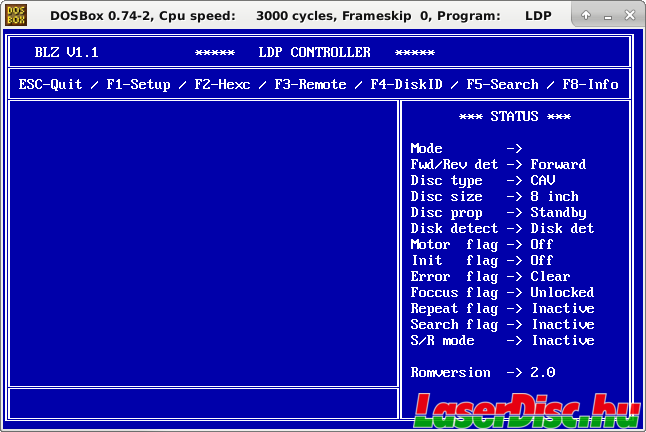
Fig. 62. LDP Commander running in DOSBox (connected to a HIL-1000).
Before you start soldering an UART, level converter etc. to add a serial port to your C1, be aware that C1's software does not necessarily send data towards or receive commands from the (non-existing) UART.
I.6. "SET UP" DIP switch on the HIL-1000
Above the RS-232C port on the HIL-1000 there is a DIP switch labeled "SET UP" with 10 switches.
It is possible to switch between "consumer" / "industrial" mode by toggling switch 8 (ON (up) sets it to "consumer", OFF (down) sets it to "industrial").
This makes the C1's RMT-M18 work (in TEST mode too!) and also disables auto-play of discs, and probably other things can be different (maybe disables RS232 port? - just a guess, haven't tested).
I've made a fast comparison between the ROM dumps from the "Interface Control" MCUs (V2.1 vs V2.0), not much difference,
but some are I/O related. Not even sure whether those are HIL-1000/C1 differences or not, can be only because of the minor version step.
One difference is reading Port0 where the "SET UP" switches are wired through pull-up resistors (IC114 pins 49 through 56).
The DIP switch itself is on the RS-709 PCB at the back of the player, from there CN202 goes to CN112 on the mainboard of the player.
CN112 is wired thru pull-up resistors (RB101) to IC114 pins (see Fig. 59.).
This means that there's +5V on the corresponding pin of IC114 when the switch is OFF, and GND when the switch is ON.
Switch 1 goes to pin 56, switch goes to pin 49 of IC114. Switch 9-10 goes somewhere else, or not even connected, i didn't trace them (yet).
| CN202/CN112 | IC114 pins |
| 1 | 56 |
| 2 | 55 |
| 3 | 54 |
| 4 | 53 |
| 5 | 52 |
| 6 | 51 |
| 7 (autopause) | 50 |
| 8 (ind/cons) | 49 |
| 9 | GND |
Table 5. Connections from RS-709/CN202 to IC114 pins.
Haven't played around with the switches for too long, besides SW8 i only found the function of SW7.
| SW# | State | Function |
| SW8 | ON | "consumer" mode |
| OFF | "industrial" mode |
| SW7 | ON | autopause after play (works in both "industrial" and "consumer" modes) |
| OFF | no autopause |
Table 6. Functions of the SET UP switches.
II. HIL-C2EX / HIL-C2NE and HIL-C3
The HIL-C2 series brought various improvements over the C1 series, most notably that it is a dual-side player.
It also became a bit smaller, lighter, and cheaper. Inside, many improvements can be observed, more highly integrated circuits, and uses a more standard (but still proprietary) system control and mode control microprocessor (see Fig. 83.), also found in other non-MUSE players (e.g. Sony MDP-MR1).
II.1. Sony HIL-C2EX
Sony HIL-C2 was manufactured in a couple of different versions (see Fig. 63., Fig. 64. and Fig. 65.). C2EX has a
gold and grey [16] finish version.
On the back it provides the usual connectors, and something interesting (see Fig. 70.):
- 2x 2x Analog audio out (RCA)
- 1x Digital audio out (TOSLINK)
- 2x Composite video output (RCA)
- 2x S-Video output
- 1x Direct Video (BNC)
- 2x MUSE output (RCA)
- Wired remote input (jack)
- LDP1/2 switch
And, like the C1, C2EX has a "Panasonic" OEM version, with a different front panel and different remote control sold as Panasonic LX-HD20 (see Fig. 64.).
The front panel of LX-HD20 is missing the "repeat" and the "backlight" on/off button, the other buttons are rearranged (most notably the open/close button), also the LCD backlight is orange compared to the blueish/whiteish LCD backlight on the Sony HIL-C2EX.
On the back the "Panasonic" version is missing the "Direct" BNC video output and the wired remote jacks. Also the LDP1/LDP2 switch is not on the back panel, but seems to be inside the chassis according to
this webpage [17].
Inside they all seem to be almost identical, all of them use the MB-713 motherboard.
These versions are quite well-known, but what about the C2NE and C3?
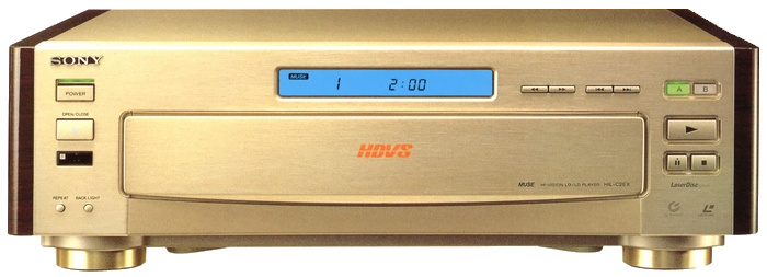
Fig. 63. Sony HIL-C2EX Gold.
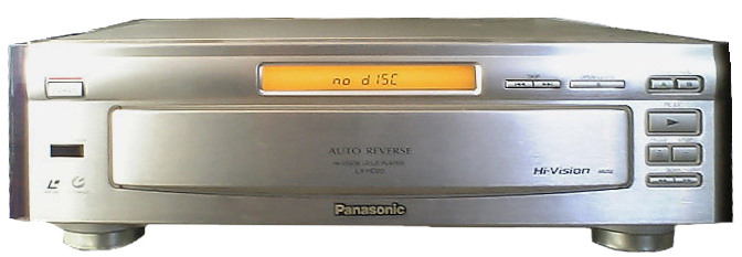
Fig. 64. Panasonic LX-HD20.
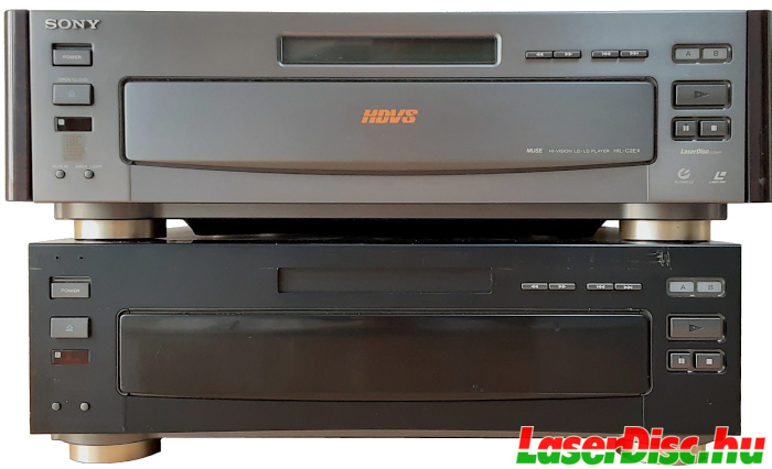
Fig. 65. Sony HIL-C2EX Grey and Sony HIL-C2NE.
II.1.1. IR Remote controls
The remote control for the HIL-C2EX is the RMT-M28 (see Fig. 66.). Seems like there was no gold version as with the HIL-C1s.
Both the players with gold finish and silver finish had the same black RMT-M28.
As for the Panasonic LX-HD20 IR remote, labeled VEQ1680 (see Fig. 67.), a totally different remote control was designed (see Fig. 68.).
This means the looks and the IR codes they send. The LX-HD20 remote uses Panasonic IR codes.
The VEQ1680 unfortunately does not work with the original HIL-C2EX, even when switching the player to "Panasonic" mode or switching between LDP1/2 modes (which mentions "OEM" on the PCB inside).
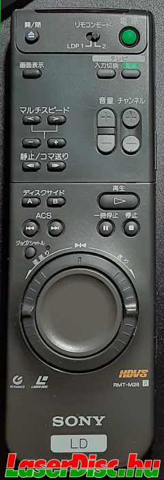
Fig. 66. RMT-M28 IR remote.
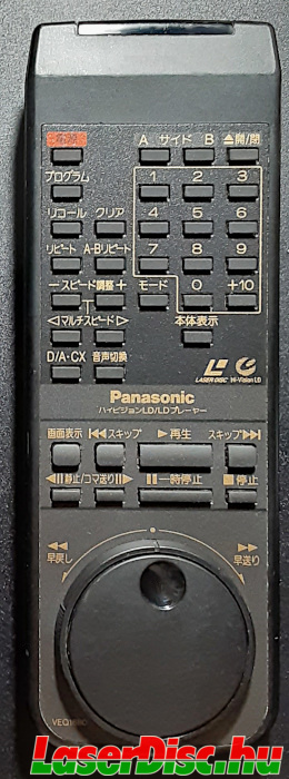
Fig. 67. VEQ1680 - LX-HD20 IR remote.
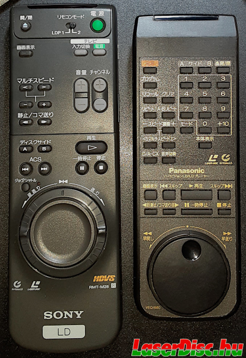
Fig. 68. HIL-C2EX and LX-HD20 IR remotes side by side.
II.2. Sony HIL-C2NE
HIL-C2NE is a stripped down version of the HIL-C2EX. It's plain black, no wooden side panels.
No LCD screen, only black plastic to cover the opening, and no SONY badge attached either (see Fig. 65. and Fig. 69.).
Only MUSE outputs, and no audio at all. One might think that the two RCA connectors on the back are for analogue audio, but they are labeled "SIRCS IN" and "STATUS OUT" (see Fig. 70.)
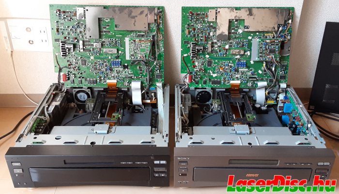
Fig. 69. HIL-C2NE and HIL-C2EX side-by-side.
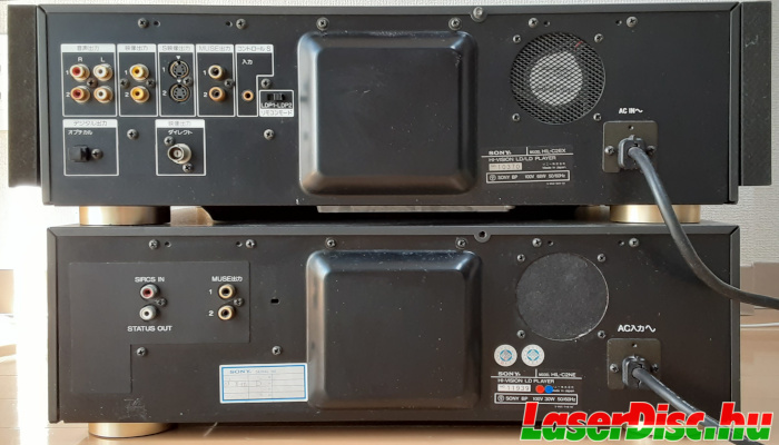
Fig. 70. HIL-C2EX and HIL-C2NE back panels.
"SIRCS IN" is for wired remote control used for receiving command from the control computer, and "STATUS OUT" is probably some serial digital signal to inform an external controller/computer about the player's current state.
"SIRCS IN" is probably the same as the "Control S Input" (コントロール S 入力) jack on the C2EX.
There are no holes for "Direct out", "Control S Input" and the LDP switch, probably it is based on the same chassis as the LX-HD20 uses.
Also the text above the power cable is in English on the C2EX (AC IN), and it is in Japanese on the C2NE (AC入力).
The VJ-705 board with the backside connectors still contains the LDP1/2 switch (SW451), but it is only accessible from the inside (switched to the left: LDP2, switched to the right: LDP1).
The IR receiver was not stripped out, so the infrared remote still works fine.
Opening it up, it becomes clear that there's no support for audio in this player.
The AU-706 board from the right side is missing, and many parts of the MB-713 (P/N 1-655-159-14) mainboard remain unpopulated (see Fig. 71. Fig. 72. Fig. 73., Fig. 74. Fig. 75., Fig. 76.).
The AB-702 audio daughterboard (the one with the "Panasonic" switch) is still there, and share the same P/N, but missing most components (see Fig. 77., Fig. 78. and Fig. 79.).
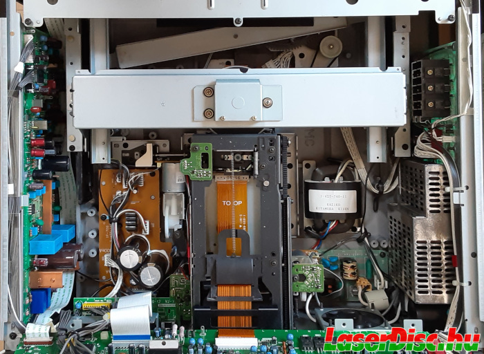
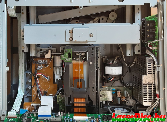
Fig. 71. Inside the HIL-C2EX and HIL-C2NE. (Move the slider to compare.)
Fig. 72. Inside the HIL-C2EX.
Fig. 73. Inside the HIL-C2NE.
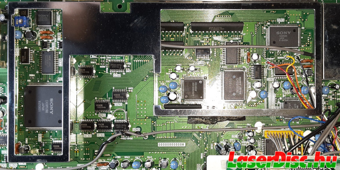
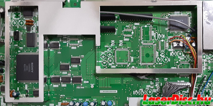
Fig. 74. MB-713 in the HIL-C2EX and C2NE - under the shielding. (Move the slider to compare.)
Fig. 75. MB-713 in the HIL-C2EX - under the shielding.
Fig. 76. MB-713 in the HIL-C2NE - under the shielding.
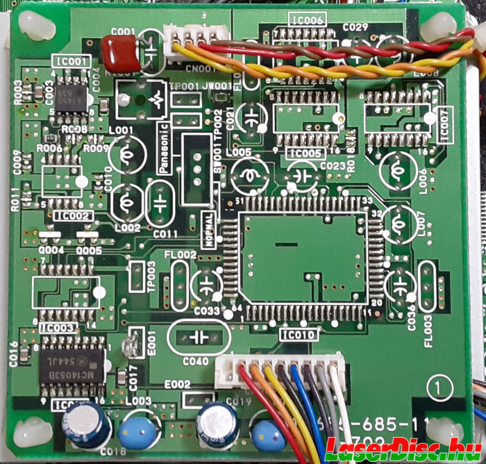
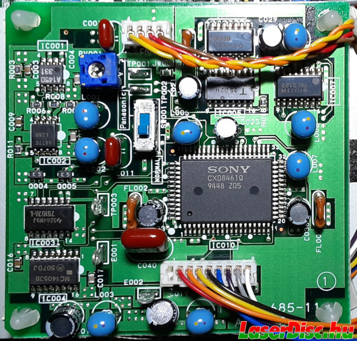
Fig. 77. AB-702 board in C2NE and C2EX. (Move the slider to compare.)
Fig. 78. AB-702 board in C2NE.
Fig. 79. AB-702 board in C2EX.
Probably you can still have sound by extracting it from the MUSE signal when using Hi-Vision discs, but with ordinary NTSC discs there's no option for sound.
Two big caps at the end of the tray were also left out.
The mainboard (MB-713) is basically the same (except the omitted components) as in the HIL-C2EX, the part number is a bit different, but probably that only means the revision number.
The C2NE uses 1-655-159-14, i've encountered 1-655-159-12 and 1-655-159-13 in C2EX players.
The fans are also a bit different in C2EX and C2NE, probably the airflow direction is reversed in the two players (i haven't confirmed this, just a guess), C2NE also has something like a filter in front of the fan
(see Fig. 80. and Fig. 81.). Also, C2NE's fan always start spinning when the player is turned on.
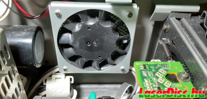
Fig. 80. Fan in the C2EX.
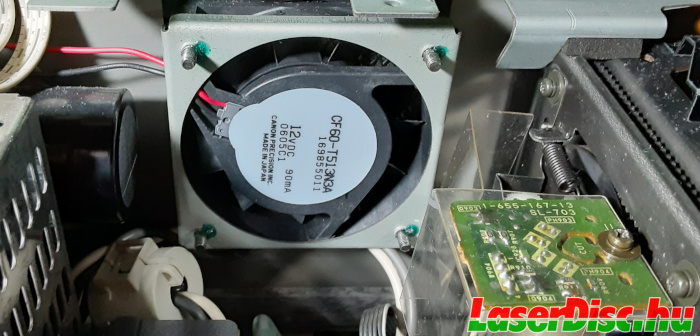
Fig. 81. Fan in the C2NE.
C2NE's SL-703 board on the pickup assembly frame has an additional protective transparent plastic cover. Also on the top of it there's an additional protective/guide rail plastic (see Fig. 82.).
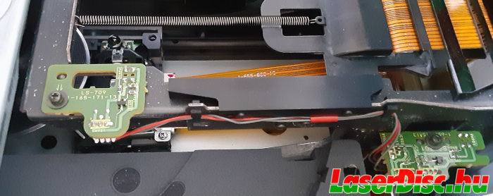
Fig. 82. Additional protective/guide rail plastic.
II.2.1. "STATUS OUT" connector
This connector goes through some amps and an optocoupler to the pin 53 of the system control microprocessor (IC1 - MB89094).
The "STATUS OUT" connector is connected to pin 2 of CN451 on the VJ-705 board, and from there it goes to CN501's pin 2 on the MB-713.
CN501 pin 2 is then patched to pin 53 of IC1 (see Fig. 83.), see the blue wire on Fig. 84.
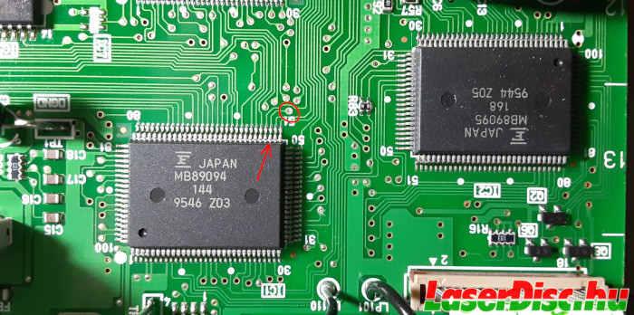
Fig. 83. IC1 pin 53 - "Status out".
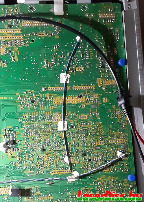
Fig. 84. "Status out" patch wire.
According to the pinout for this IC found in the service manual of the C2EX, this pin is... "not connected/unused".
Anyway, hooking up a scope on the "STATUS OUT" i could not see anything which resembles data signals (constant 5V on pin 53 when the unit is powered on).
Maybe it needs to be triggered with commands coming in through "SIRCS IN", or just this player is malfunctioning.
C2EX also has traces to pin 53, so, one can easily try to add "STATUS OUT" to a C2EX.
And, the "Mode Controller" (IC2 - MB89095) pinout mentions RS232 data and control pins, so probably it includes an UART and it could be worth investigating whether it is possible to use these pins to add an RS232 interface to a HIL-C2xx or not.
II.2.2. NEC Fish Club
So, why was the C2NE version made?
This player was the one, which was used in the NEC Fish Club 魚八景 (NEC SH1011-xx, see Fig. 85.), where, obviously, there was no need for sound processing, so everything unnecessary was stripped out to save costs.
A
thread on LDDB forums [18] reinforces this special use case of the C2NE, and also points to a movie (
Gorgeous / Under Control [19]) where you can see the NEC Fish Club in action for a few seconds.
The movie is from 1999, so the NEC Fish Club was still popular years after its release (around mid-1995).
Fig. 86. shows the control panel of the NEC Fish Club, the disc tray can be seen on the right side.
Fig. 87. shows the cabinet from the back side with the covers removed, the back of the player can be seen at the bottom of the cabinet.
(Maybe NE in HIL-C2NE stands for NEC?)
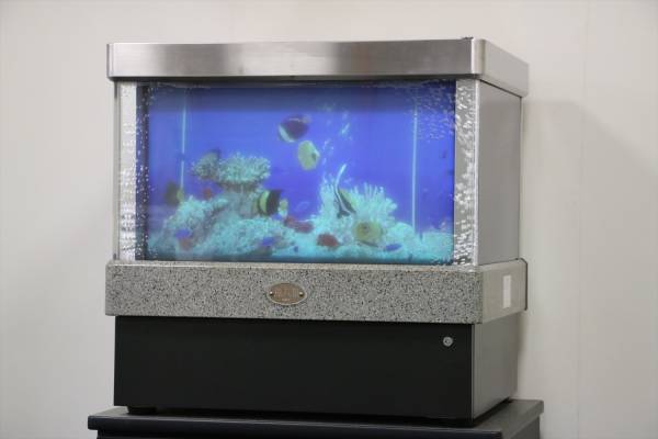
Fig. 85. NEC Fish Club
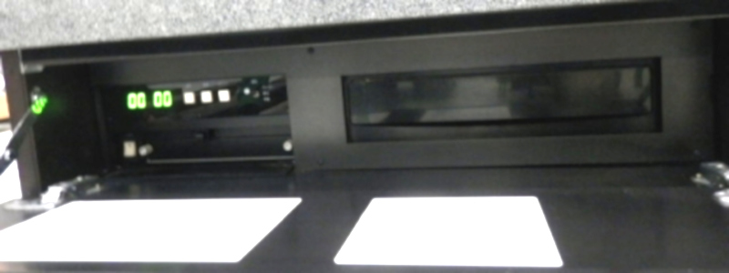
Fig. 86. NEC Fish Club (under the screen) control panel (left),
LD player's tray (right)
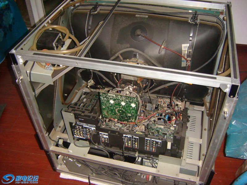
Fig. 87. NEC Fish Club from behind.
Back of the player can be seen at the bottom of the chassis.
II.3. Sony HIL-C3
The mystery player... Some speculate that this player was intended to be an initial US market Hi-Vision player, but was cancelled, and this could have been a prototype.
A short English language service manual (only Japanese language versions exist for HIL-C1/C2EX) for adjustments is floating around on the web, so that could fuel this speculation.
Two of them showed up on Yahoo Auctions, one in 2013 (see Fig. 88.) and one in 2021 (see Fig. 89.), and these photos show that it is just like the HIL-C2NE.
Also the aforementioned service manual gives MB-713 as the mainboard of the player, and RMT-M28 as the remote control which are the same for the C2EX/C2NE, and the drawings of the player also match with C2.
That would explain the short English service manual for performing some adjustments, which also makes a tiny reference to NEC in the equipment list:
"MUSE Reference disk (NEC specification)".
So actually, my guess is that, <speculation> it's more like that this player is just a slightly upgraded version of C2NE and was used in the US (or Japan + US compatible, 2in1?) version of the
NEC "Fish Tank" [20] </speculation>.
And the two C3 players on YAJ were salvaged from such NEC Fish Club SH1011-0x, just like the C2NE i have.
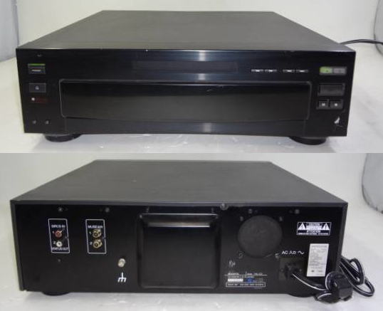
Fig. 88. HIL-C3 Front/Back - YAJ 2013.
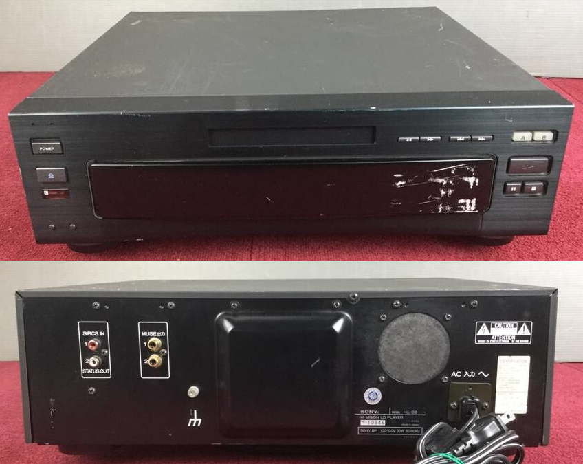
Fig. 89. HIL-C3 Front/Back - YAJ 2021.
Probably the HIL-C2NE and HIL-C3 are very similar or even identical, maybe except for the power supplies, which, according to the labels on their back, are rated 100V (C2 - See Fig. 90.) and 100-120V (C3 - See Fig. 91. and Fig. 92.).
But actually that does not necessarily mean that the power supplies are different, maybe C2NE is also fine with 100-120V, and only the sticker is different. As i don't have a C3 i cannot confirm this, so don't try this at home.
C3 has a bit nicer back panel around the 2x2 RCA connectors (a white frame painted around them), it looks like the metal back plate was modified, unlike the C2NE, which has just a plastic cover on top of the original back plate. A ground connector was also added on the C3, which the C2NE does not have.
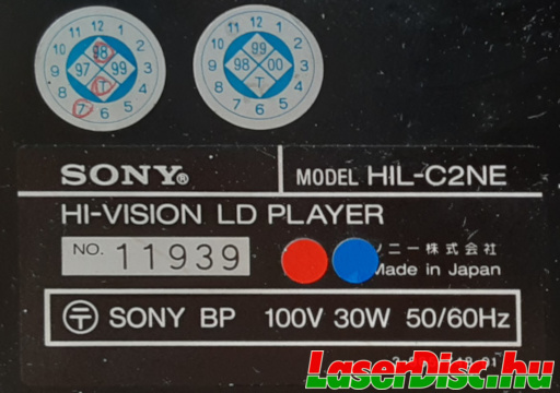
Fig. 90. HIL-C2NE Sticker
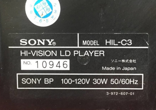
Fig. 91. HIL-C3 Sticker - YAJ 2021
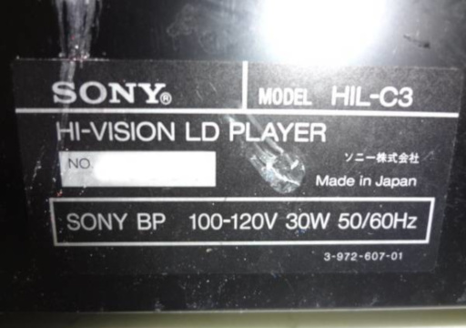
Fig. 92. HIL-C3 Sticker - YAJ 2013