AC3B T-VWV143 / T-VNP411A (GXX1135)
This short document is about the T-VWV143 / T-VNP411A AC3RF out mod board I have came across. I found this board (box) in a Japanese Pioneer LD player.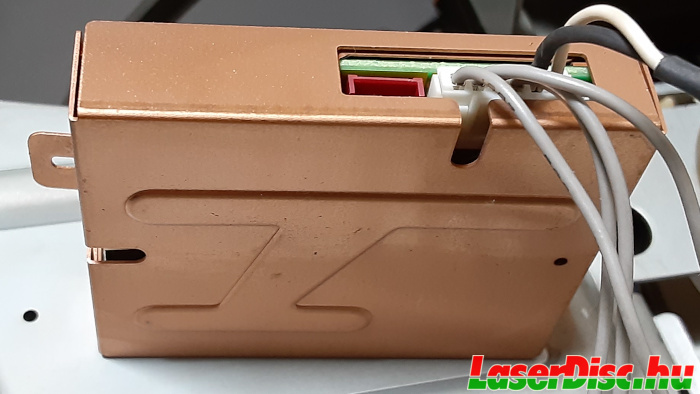
Fig. 1. VWV143 in its copper box.
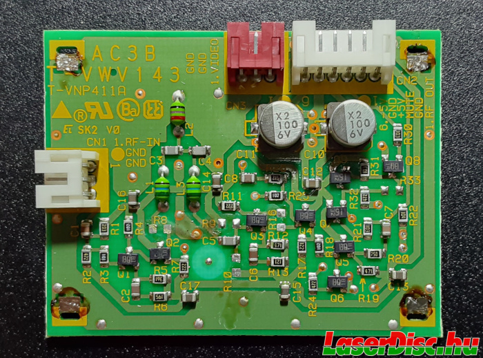
Fig. 2. VWV143 top view #1.
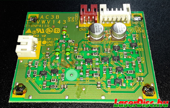
Fig. 3. VWV143 top view #2.
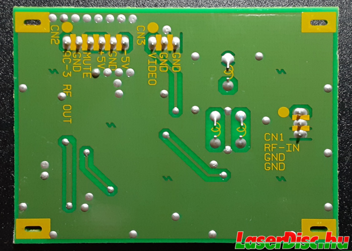
Fig. 4. VWV143 bottom view #1.
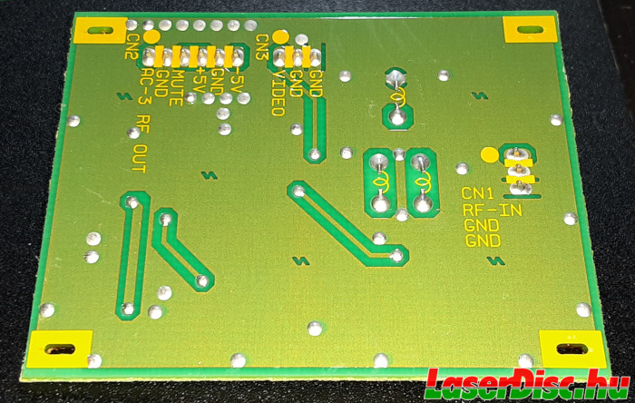
Fig. 5. VWV143 bottom view #2.
Later it turned out that's it's actually a real Pioneer upgrade kit: GXX1135 (thanks to Julien@lddb).
It is housed in a nice copper box (Fig. 1.), and what is interesting that it has a "Video" input. Actually, the RF video signal (or even the unfiltered raw RF signal) goes there. There are 3 connectors on the board:
- CN1 (left, white): 3-pins for the audio RF
(pin 1: RF-IN, pin 2-3: GND) - CN2 (top, white): 6-pins for power/mute signal/output RF signal
(pin 1: AC-3 RF OUT, pin 2: GND, pin 3: MUTE, pin 4: +5V, pin 5: GND, pin 6: -5V) - CN3 (top, red): 3-pins for the video RF
(pin 1: VIDEO, pin 2-3: GND)
In this configuration, the board works (yes, actually it works perfectly!) even when the video RF input is not connected. The only difference i could observe, that when the video RF is connected, the max. peak-to-peak voltage of the AC-3 RF out signal drops slightly, so the output is attenuated a bit. Maybe, then the function of the video RF input is to control the amplification of the audio RF signal. Again, just a guess.
Anyway, it looks professional, and the box is quite fancy too (see Fig. 6. and Fig. 7.).
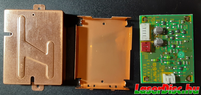
Fig. 6. VWV143 with open box - top view.
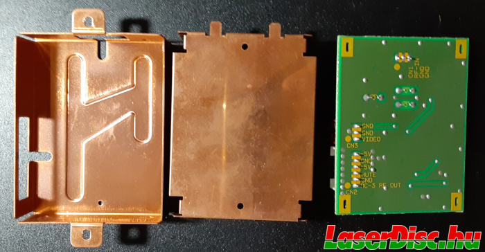
Fig. 7. VWV143 with open box - bottom view.
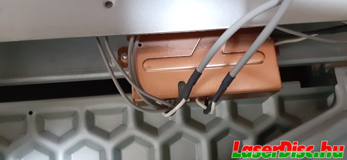
Fig. 8. VWV143 in a HLD-1000.
Do you know more about this one?
Please contact me then, thank you very much!